
 WORLD RECORD RB - 6 ABLE " RUNNING " 365 DAYS ( 12 MONTH MORE )
 Sunday, November 24, 2013
 Unknown

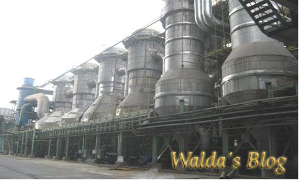
 Recovery Boiler - 6 is one of the two boiler units operating in the RB - 1 ( RB
- 5 and RB - 6 ) . Boiler is located in the area currently only Riau.And
Recovery boiler - 6, listed as one of the boilers are capable of operated for
365 days , 12 months without any stop engine and trip since September 10, 2012
until now .
Recovery Boiler - 6 is one of the two boiler units operating in the RB - 1 ( RB
- 5 and RB - 6 ) . Boiler is located in the area currently only Riau.And
Recovery boiler - 6, listed as one of the boilers are capable of operated for
365 days , 12 months without any stop engine and trip since September 10, 2012
until now .


