
 BURNER MANAGEMENT SYSTEM (BMS)
 Wednesday, May 08, 2013
 Unknown

Technical data

3. Port view

4. Damper


 I. Instructions
Start oil burner and burner management system

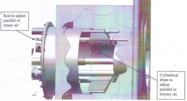
Figure1. View from side

Figure2. View from front

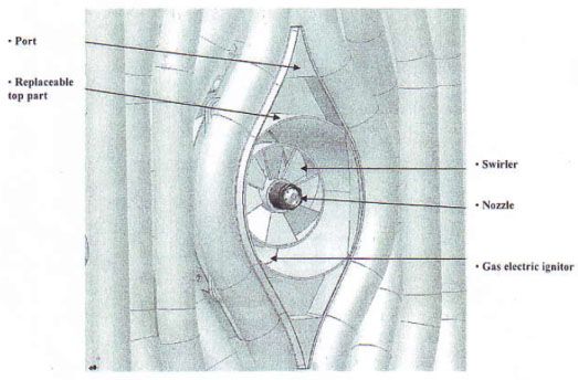
Figure3. View of fort, swirler and nozzle
By changing the amount rotary or parallel air, you change the looks upon the oil flame. With rotary air you will have a shorter and wider flame. Depending on the conditions in the furnace close to the burner you’ll have changes on the looks of the oil flame and also changes in the signal quality from the flame scanner.
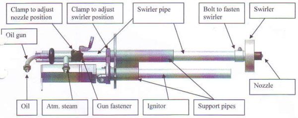
Figure 3. Oil gun with front door, swirler and nozzle.
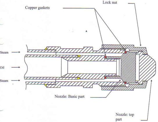
Figure 4. Oil gun nozzle.
- Capacity oil 500 kg/h
- Oil pressure ~ 6 bar
- Combustion air pressure ~ 1200 pa
- Atomizing steam pressure ~ 10 bar
- Capacity, ignitor 125 kw
- Gas pressure ignitor inlet ~ 0.1 bar
- Air pressure ignitor inlet 1.0 kpa
Burner assembly
1. View for right side

3. Port view
4. Damper
5. Front part with oil gun and ignitor
6. Oil gun nozzle
 I. Instructions
1. Preparation before operation
- Fulfil before interlocks
- Open the oil header valves to start circulation of oil to the burners
- “burners permitted” should be indicated
- Fulfil interlockings for boiler purge unless “liquor fire” or “burner in operation” is indicated
- Open gas header valves
- “permission to start” should be indicated
2. Start of burner
- Make a insfection of burner opening into the furnace and clean it if necessary
- Mount a well cleaned oil gun into the burner and connect hoses for for oil and atomizing medium
- Insert burner into operation position
- Open manual valves for oil, steam and ignitor gas
- Adjust combustion air pressure to ~500 pa
- “burner ready to start” should now be indicated
- Press “start” push button
- When “burner in operation” is indicated, adjust the combustion air to ~1200 pa and set the amount of rotary or parallel air
- Rod the burner port frequently operation
3. Scavenge and stop of burner
- Check if gas header valves is open
- Check local manual gas valve is open
- Press push button “stop & scavenge in progress” is not indicated any longer
- Refract the burner to retracted position
- Close manual valves for oil, steam and ignitor gas
- Disconnect hoses for oil and atomizing steam
- Adjust the combustion air pressure to ~250 pa. This will maintain enough cooling of the burner and winbox
- Dismount the oil gun and clean the nozzle according to recommendations
4. Separate scavenge of burner gun
A separate scavenge is done when a burner tripped or if the operator like to do a extra scavenge to clean the oil gun better.
- Check if gas header valves is open
- Check if local manual gas valve is open
- Push the burner into inserted position
- Press push button “stop & scavenge
- Wait for ~30 seconds until ” scavenge in progress” is not indicated any longer
- Retract the burner to retracted position
- Close manual valves for oil, steam and ignitor gas
- Disconnect hoses for oil and atomizing steam
- Adjust the combustion air pressure to ~250 pa. This will maintain enough cooling of the burner and winbox
- Dismount the oil gun and clean the nozzle according to recommendations.
4. Burner tripped
- Check first out information
- Make changes according to first out information if possible.
- Wait until boiler purge or reignition delay time is done try to start the burner again or make a separate scavenge of the oil gun.
II. Maintenance instruction
1.Cleaning of the oil gun nozzle
a. Clean holes in the nozzle with a suitable tool.
b. Clean the gap with a thin piece of metal.
- Check if all opening in the nozzle base part is clean and that both copper gaskets are ok.
- Check the status upon the locknut threads and threads on top of the oil gun.
- Assemble the nozzle top part and locknut with the oil gun
Note: don’t use exesive force due to problem during disassemble when the oil gun is hot
- Put the oil gun to storage or back into the burner.
Start oil burner and burner management system
1. Oil burning equipment, in general
The boiler is equipped with 3 straight burners whose function are:
- Heat the boiler and create conditions for a safte liquor light-off, increase steam, -pressure before start of the liquor firing.
- Support the liquor-firing when necessary
- Enable a fast burn down of the smelt bed
- Produce steam
The start burners are oil fired and are located in the secondary air register. They are equipped with individual air registers and air dampers. The oil is atomized by pressure steam (10 bar). The combustion air is supplied by the secondary air fan.
The burners are semi automatic. Manual insertion of oil burner gun and ignitor is needed before start up. When the gun is mounted and put into operation position the BMS will run the start up sequence upon order from operator.
Each burner is equipped with a gas-electrical igniter. An air fan supplies the igniters with combustion air and the flame scanner with cooling air. The cooling of the flame scanner must not be shut off more than for very short periods of time when the boiler is hot.
2. Oil System
The oil system consists of the following main components
- One manual valve to isolate the start burner oil system
- Automati main shut off valve. The valve is interlocked with the burner management system and automaticly shut off when the following occurs, emergency stop, emergency shut-down procedure, “fail to close” error on an individual safety shut-off valve.
- Flow measurement
- Flow controller for measuring of the oil flow to the burners. The oil flow is calculated as the difference between this oil flow and the oil flow in the oil return pipe.
- Pressure control valve to reduce and maintain a oil pressure ~8 bar.
- High pressure gauge, which interlocks the burners when the oil pressure gets to high (overload).
- Low pressure gauge, which interlocks the burners when the oil pressure gets to low (to avoid operation during problematic conditions)
- The following main components are located between the main oil circuit and the individual burners:
- Manual shut off valve for oil. Close this valve before removal of oil burner gun.
- Double automatic shut off valves that close when interlocks are activated. If these valves are not “provent” closed when they are supposed to, the error “failure to close” occurs and the main oil shut off valves close automatically.
- Automatic valve that opens between the oil to the burner and the atomized steam for cleaning of the oil burner gun and hoses.
- Pressure gauge for indication of oil pressure in oil burner gun.
- The following components are located in the oil return pipe:
- Low pressure gauge for oil. A warning is issued at to low temperature.
- Flow measurement
- The recirculation valve is interlocked the same way as the main oil shut off valve (see above).
- Check valve which prevents oil to reach the burners from the oil return pipe.
- Manual valve which can isolate the oil pipe around the boiler from oil flow.
3. Atomizing system
The oil is atomized by medium pressure steam (10 bar)
The atomizing system consists of the following components:
Each burner is equipped with the following components:
- Manual valve and check valve. Close the manual valve for removal of the oil burner gun.
- Always remove the atomizing hose first. Always connect it last.
- Low pressure gauge that interlocks the operation of the burner when the pressure in atomizing steam gets to low.
4. Combustion air system
The combustion air is supplied from the secondary air fan och and the flow is regulated by the damper.
Each burner is equipped with:
- Pressure gauge for the pressure of the combustion air fed to the burner.
- Low pressure gauge for the air that interlocks the burners operation.
5. Ignition gas system
The ignition system supplies the gas-electric igniters with gas during start-up. It consists of the following components:
- Self actuating valve that brings down the pressure from the bottles to 0.1 bar.
- Two shut off valves and one ventilation valve in between. The valves controlled by the same signal. The valves are interlocked by the safety system.
- Two pressure gauges: one high- and one low pressure gauge that interlocks the gas header at too high or low pressure.
- Pressure gauge for indicationof gas pressure in igniters. The pressure should be 0.05 – 0.15 bar.
- The gas header then leads to each and every burner and each burner is equipped with the following:
- Manual valve that shall be shut off for maintenance or service of the igniters.
- Automatic shut off valve, controlled by the burner safety system.
6. Ignition and cooling air system
The ignitors combustion air is supplied by the cooling air fan. The cooling air fan also supply purge and cooling air to flame scanner on each oil burner. The system consists of the following components:
- Low pressure switch that interlocks start-up of igniter at to low air pressure. Burnes operation will not be affected by the low pressure switch, that it is interlocked against start-up and oil gun scavange.
- Local pressure indicator. Pressure during operation of fan should be ~4 kPa.
- The air header then divides with one pipe to each burners is equipped with:
- Manual valve for turning on/off the air. Note that the valve should only be closed during maintenance and service because the igniter and flame scanner need cooling.
- Regulator for adjustment of air pressure to igniter. Proper air pressure varies in different installations due to different conditions in different boilers. The pressure to the igniters is set at start-up of the burner system. A check of correct air pressure can be done by looking at the flame. The most common error is too much gas flow in relationto the air flow. Too much gas flow puts the flame out. To little air flow gives a yellow flame and too much air flow gives a pinkish blowtorch looking flame. Incorrect air /gas flow does not give flame indication from the igniter (igniter in operation).
7. Burner Design
7.1 Design
Start burner design described below:
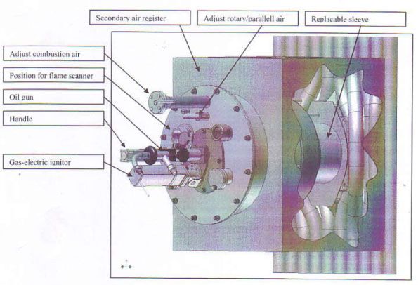
Figure1. View from side
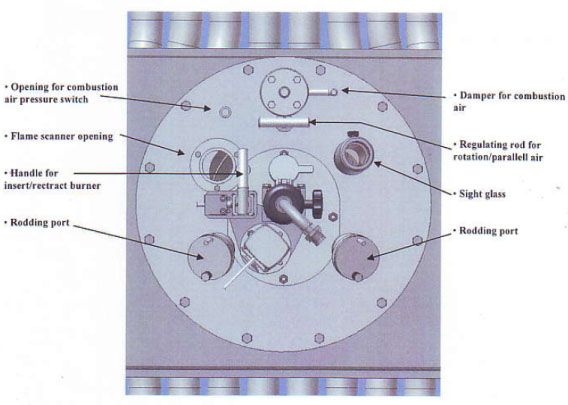
Figure2. View from front
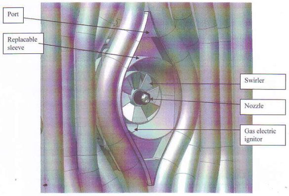
Figure3. View of fort, swirler and nozzle
The burner is a oil fired burner with a separate air register of parallel air type. It’s nominal capacity is 500 kg/h oil.
The capacity of all burners can be adjust with the pressure control valve in oil header line. (500 kg/h should be reach at-6 bar).
Atomizing air are to be delivered to the burner at 10 bar.
Air register contains of one cylindrical drum with a front plate bolted on to the secondary air drum. The air register is mounted into the tube wall opening.
On the burner front plate there is openings for sight glasses and rodding ports. All burner are equipt with flame scanners to monitor the oil flame. This is also mounted on the front door.
The amount of combustion air can be adjust with inbuilt damper. The damper position can be adjust with the adjusting wheel palced into the front palte.
Caution! The combustion air to the burner is not to be closed totally to secure enough cooling to the burner and burner air register.
Within the burner air register there is also a damper adjusting the amount of parallel or rotary air. By positioning the cylindricaldrum with the rod implemented on the front plate, you will partly cover the rotary air or parallel air register. With the rod totally inserted you will have 100 % parallel air.
By changing the amount rotary or parallel air, you change the looks upon the oil flame. With rotary air you will have a shorter and wider flame. Depending on the conditions in the furnace close to the burner you’ll have changes on the looks of the oil flame and also changes in the signal quality from the flame scanner.
The oil gun consists of two concentric pipes, where the oil goes through the inner pipe and atomizing steam between the inner and outer pipe. The burner is connected to each medium pipe by flexible hoses with quick couplings. Each quick couplings have a inbuilt check valve to minimize leakage from the hoses when being disconnected from the burner.
Figure 3. Oil gun with front door, swirler and nozzle.
The oil gun is inserted in the swirler pipe. The swirler pipe is mounted upon the front door. The oil gun nozzle position in the tube wall opening can be adjusted changing the position of the clamp. A equal clamp can be found to adjust the swirler position in the tube wall opening. The swirler task is to create stabil conditions close to the oil gun nozzle.
The distributed to the furnace by a nozzle described above. Thrue the nozzle the oil will be atomized by midpressure steam and create a fine mist of oil. The type of nozzle is written on to the nozzle base.
Figure 4. Oil gun nozzle.
7.2. TECHNICAL DATA
Capacity , burner 500 kg/h
Oil Pressure ca 0,6 MPa
Combustion air pressure ca 800-1500 Pa
Atomizing steam pressure ca 1,0 MPa
Capacity, initor 8 kg/h
Gas pressure, ignitor ca 15 kPa
Combustion air ignitor ca 2 kPa
7.3. Maintenance And Service
In order to achive suitable combustion it is important to make sure the nozzle is not cloed up dirt or worn down.Cloin up of single holes in the nozzle can affect the combustion.
To remove of the nozzle, the nut should be removed first. (See Figure 4). In order not to damage the threads it is recommended that the oil burner gun is cooled of before dismantling. When the nut has been removed the top part of the nozzle can be removed. After that the nozzle base part can be dismantled from the gun.
Note that the surfaces between the top and base part of the nozzle have a sealing affect, therefore handle these gently.
Clean the nozzle and make sure the holes and clean from dirt. When assembling the nozzle, make sure the 2 two differentcopper gaskets for oil and steam are in place. Also make sure the threads outside and inside of the pipe are clean and lubed with heat resisting lube.
NOTE! Prior to assembling of the nut, there is a gap between the guns outer pipe and the nozzle. This is because the nut centers the nozzle and the uns inner pipe. The gap is tightened when the nut is assembled.
The nozzle position in relation to the swirler can be adjusted by a clamp rin mounted on the oil burner un. Recommended distans between the top of the nozzle and the front of the swirler is approximately 35 mm.
Swirler position in the burner opening has great affect of the burners flame stability. The support pipe of the gun and the swirler should be retracted as far as possible without the oil mist hitting the port opening. Swirler position in the burner can be adjusted by a clamp ring mounted on the swirler pipe.
When the burner is not in operation the swirler and gun is retracted in the air register and the cooling air from the secondary air fan is kept on. Recommended coolin air pressure is approximately 250 Pa.
 Posted in: POWER PLANT


2 komentar:
Hi nice blog post you are providing good information about Low Air Pressure Burner thanks for this information.
Burner Management system
Really impressed! Very informative blog.
Post a Comment
Thank you for your comment