
 THE STEAM TURBINE
 Tuesday, April 23, 2013
 Unknown


1. SAFETY:
a. Security for the people (person). In this case to
avoid the things that can cause an accident.
b. Security for equipment (equipment) prevent damage to
the equipment with respect to the implementation of the operation as
recommended by manufacturer (Manual Book) as well as good maintenance.
2. RELIABILITY / reliability of the unit by way of
maintaining continuity of operations.
Avoid the trip unit by mistake and shut down operations
due to equipment malfunction. In this case of course, supported by good
maintenance.
3. Effeciency:
Carry out operations in order to achieve a high EFF by
following operating instructions as recommended by manufacturer.
Before we discuss further steam turbine, it is good we
need to know:
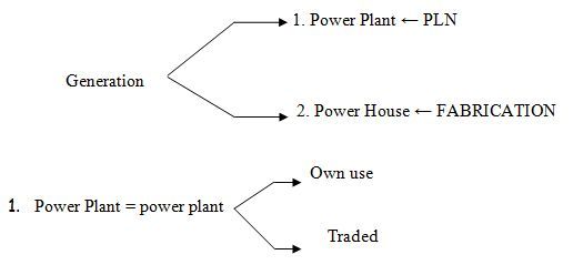
2. Power House = use his own power plant →
↓
- Factory
- Offices
- Housing
- Schools
- Mosques and Churches
- etc
Steam Turbines: is a first mover that converts the steam
into potential energy kinetic energy. Further kinetic energy converted into
mechanical energy in the form of the turbine shaft rotation
CLASSIFICATION OF STEAM TURBINE
Steam turbines can be classified into categories
berbedatergantung in construction, heat reduction process, the conditions of
the beginning and end as well as its use in industrial steam as follows:
1. According Total Pressure Level:
a. Turbine Atua one level with one more level of speed
that is usually a small capacity. The turbine is mostly used to drive
centrifugal compressors and similar machines.
Example: Turbine DE-LAVAL (Fig. 1)
b. Impulse turbine with a single pressure level and the
level of velocity (speed) double (compound). The system is applied to a single
rotor turbine with curtis. (Fig.2)
c. Impulse turbine with multiple pressure levels and the
rate is applied to the system velocity Rateau turbine. (Figure 3)
d. Impulse turbine with multiple velocity levels of
stiffness with this system applied to the dual rotor turbine Curtis (Figure.4)
e. Turbine system using a combination of Curtis-Rateau
(Fig.5)
f. Reaction turbine with multiple levels and a level of
velocity. The system is applied to the turbine Parson (Figure. 6)
g. Impulse turbine combination - reaction. This system is
applied in combination Curtis-Parson (Figure.7)
h. Reaction turbine with a rotor and a double round. The
system is applied to the turbine Ljungstrom (Fig. 8)

Figure 1. Turbine Impulse Pressure Level and Velocity
Single
Figure 2. Turbine Impulse Pressure Levels With Velocity
Single and Dual Rate (Compound)
Figure 3. Turbine Impulse Pressure Level One Double and
Velocity
Figure 4. Turbine Impulse Pressure Level and A Level Dual
Velocity
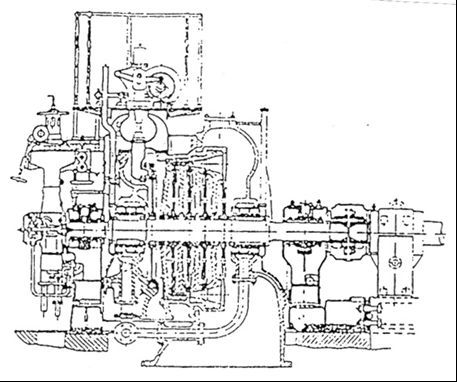
Figure 5. Turbine Combination
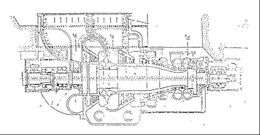
Figure 6. Reaction Turbine With Pressure Level Double and
One Velocity level
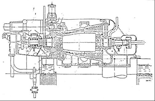
Figure 7. The combination of impulse turbines - Reaction
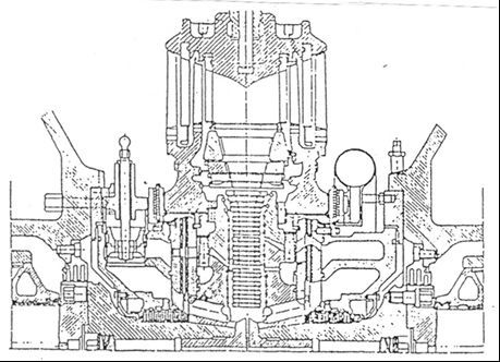
Figure 8. Reaction Turbine With Rotor and Round Doubles
2. According to the Steam Flow Direction:
a. Axial turbine, the steam is flowing in a direction
parallel to the axis of the turbine.
b. Radial turbine, the steam is flowing in a direction
perpendicular to the axis of the turbine.
3. By Number of Cylinders:
a. Turbine Single Cylinder
b. Turbine Double Cylinder
c. Three turbines slinder
d. Turbine Four Cylinder
4. According Methode settings:
a. Turbine with strangulation settings (throttling) the
fresh steam entering through one or more (depending on power generated)
strangler valve operated simultaneously.
b. Turbine with a steam nozzle arrangement fresh go
through two or more regulators opener (Opening regulators) are sequential.
c. Turbine with setting step (by-pass governing) that
besides the fresh steam supplied to the first level also directly channeled to
one, two or even three mid-level turbine.
5. According to Steam Action Principle:
a. Impulse Turbine, its potential energy converted to
kinetic energy in the nozzle or the passage formed by the stationary blades
(blade guide) adjacent and in the motion blades (blade movie) kinetic energy is
converted into mechanical energy.
b. Reaction turbine steam expansion axial blade passes
between both blade guides and blade motion. Each level takes place almost at
the same rate.
c. Radial reaction turbine without blades steering
silent.
d. Radial reaction turbine with blade guides that are
silent.
6. According Process Heat reduction:
a. Condensing turbine (condensing turbine) to the
regenerator, in this type of steam turbine at a pressure lower than atmospheric
pressure is applied to the condenser, the vapor also dicerat addition of medium
levels of filler kettle to heat water, the amount of penceratan usually 2 to 3
to 8 - 9.
Latent heat of exhaust steam condensation during the
turbine's all gone.
b. Condensing turbine with one or two penceratan of the
medium at pressure levels for industrial purposes and heating.
c. Pressure turbine opponents (Back Pressure Turbine)
exhaust steam is used for heating and industrial purposes.
d. Overlap turbine, the turbine is also opposed to the
type of turbine pressure difference that is still used for the exhaust steam
turbines condensing medium and low pressure.
e. Pressure turbine opponents (Back Pressure Turbine)
with penceratan steam from medium levels at a particular pressure, in order to
supply steam to consumers at various pressure and temperature conditions.
f. Low pressure turbine (pressure Discard) exhaust steam
from steam engines used for power generation purposes.
g. Pressure turbine mixed with two or three levels of
pressure with exhaust steam supply to the medium levels.
7. According to Steam Conditions Log In Position:
a. Low pressure turbine (Low Pressure Turbine) pressure
(1.2-2.0) atm.
b. Intermediate pressure turbine (Middle Pressure)
pressure (2-40) atm.
c. High-pressure turbine, the vapor pressure (40-170)
atm.
d. Very high pressure turbine, the steam pressure
(170-225) atm.
e. Super critical pressure turbine, the vapor pressure
exceeds 225 atm.
8. According pemekaiannya industry:
a. Stationary turbine with a constant rotational momentum
is mainly used to drive the alternator.
b. Stationary steam turbine varies with the rapidity
which is used to drive the blower, turbo, air dealers (Air Circulator), pumps
etc..
c. Turbine is not stationary with varying rapidity,
turbines of this type usually used steamers, ships, railroad locomotives
(Locomotive turbo)
All types of turbines that have been described above are
dependent on the rapidity turn can be connected directly or through a reduction
gear with engine-driven machine.
STEAM TURBINE in use
Many industries use steam for industrial purposes except for process heat,
or mechanical energy is also power to run the plane. Because of the special
nature of the heat release time, the heat exchanger to heat during the process
handover to the medium to be heated. Mechanical power of steam addition can be
useful if the process temperature and high vapor pressure, further expands in
the turbine pressure allowed an opponent to the required pressure.
Turbine Industry Divided Over Five Group:
1. Pressure turbine opponents (Back Pressure Turbine)
2. Condensing turbine (Condensing Turbine)
3. Extraction turbine / drain (Extraction Turbines)
4. Turbine combination (Mixing Turbines)
5. Turbine waveguide.
ad.1. Pressure Turbine Opponent:
pressure turbine opponents used when an industry that
requires multiple steam as a source of potential energy as well as energy
sources for processing purposes.
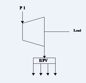
Figure 1. Pressure Turbine Opponents
ad.2. Condensing Turbine:
Condensing turbine is used when all the energy is used to
generate steam power, while the former steam condenser is condensed into the
opponent under pressure low enough to produce a high power, condensate water
can be recirculated into the kettle.
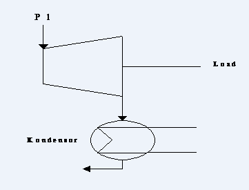
Figure 2. Condensing Turbine
Ad.3. Turbine extraction:
Extraction turbine is divided into two types:
1. Extraction condensing turbine
2. Pressure extraction turbine opponents
Extraction condensing turbine, operating with dual vapor
evaporation, which is in addition to power generation, as well as to supply the
necessary steam extraction purposes.
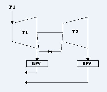
Figure 3. Kettles turbines - Pressure Fight
ad.4. Mixed turbines (Turbine Mixing):
Turbine mixture also known as mixed pressure turbine
(Mixed Pressure Turbine).
Low or medium pressure steam is used processed blended
into the next level of a condensing turbine or a turbine pressure to boost
power turbine opponents.
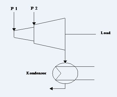
Figure 4. Mixed Turbines
ad.5. Turbine Pandu:
The turbine is also called pressure turbine turbine
opponents because it is associated one or more existing turbines, specifically
planned for a low initial pressure.
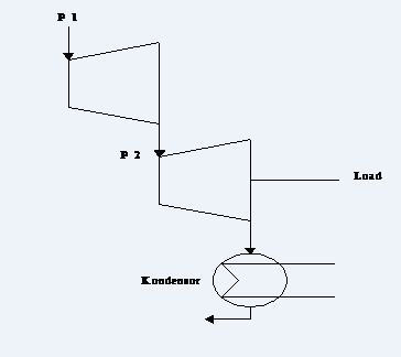
Figure 5. Turbine Pandu
STEAM TURBINE PARTS
Steam turbine consists of several main parts such as:
1. Turbine house (Casing)
2. Rotating part (rotor)
3. Blades
4. Cushion
ad.1. Turbine house (Casing)
A turbine casing houses that make up the room (chamber)
around the rotor to allow steam to flow across the blades.
Pedestal that serves as a buffer to put the pads are
attached to the rotor casing. Generally one pedestal tied (Anchored) kepondasi
dead, while others are placed on rail launcher (Sliding Feet) so that the
casing to move freely. Due to the effect of expansion and contraction
(Contraction), usually pedestal foundation is tied to the low pressure side of
the pedestal or side adjacent to the generator (Generator End), while the other
side is left to be able to move freely. When the casing and rotor temperature
rises, the entire turbine construction will expand.
By placing one above the pedestal rail launcher (Sliding
Feet), all turbine parts can move freely as it expands and as illustrated in
Fig.1.
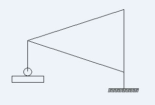
Figure 1. At the foundation casing construction
Configuration Casing:
1. Casing intact
The entire casing is an integral part. Generally applied
to the construction of small turbines.
2. Separate casing (Split Casing)
Turbine casing is 2 separate parts horizontally and
connected into one binder bolts.
The second part of the casing, respectively called the
upper casing (Top Half) and the casing bottom (Bottom Half). This construction
is more widely used because of demolition and installation is relatively easy.
Design Casing:
Turbine casing distinguished 3 categories:
a. Single Casing
b. Double Casing
c. Tripple Casing
Almost all of today applying steam turbine casing design
double or triple casing for the period startnya faster, smaller problems of
differential expansion and maintenance is relatively easy.
ad.a. Single Casing
Generally applied to the design of the old turbines and
small capacity. Nevertheless turbines currently still no single casing design
that applies mainly to the turbines for propulsion boiler water pump filler
(BFPT). When this design is applied to large turbines, the turbine casing will
be very thick so it takes quite a long time in the period of
"warming" when it start to reach the full expansion.
This is because the walls are very thick casing and only
heated by steam from one side of the inner side. These conditions resulted in
substantial temperatu difference between the inner surface of the outer casing
to the surface.
Thus the time required for temperature equalization
becomes longer. Illustration of single casing turbine can be seen in Fig.1.
following.
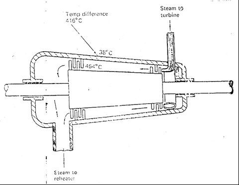
Figure 1. Single Turbine Casing
When the temperature of incoming steam turbine 454 ° C,
then when the start-up temperature of the inside of the casing is also
approaching 454 ° C. While the outside of the casing temperature is outside air
temperature or about 38 ° C.
Thus, at the start there is a difference in temperature
between the inner surface of the outer surface at 416 ° C.
The inside tends to expand while the outer portion is
relatively not going to expand.
When the temperature difference is large enough, then in
extreme conditions can cause cracks in the casing is quite thick.
ad.b. Double Casing
In double casing design consists of 2 turbine casing for
each cylinder. Thus, the thickness of each - each case is only half the
thickness of a single casing. Thus the distribution of heat and expansion
process becomes faster.
Besides, as each segment becomes lighter casing, then
maintenance becomes easier or faster.
As an illustration for tirbin double casing can be seen
in Figure 2 below.
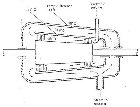
Figure 2. Double Turbine Casing
When the temperature of 460 ° C steam turbine atmospheric
temperature being 38 ° C the difference in steam temperature 422 ° C. Double
casing design advantage is that the Δt at 422 ° C is divided in 2 incoming
steam casing, the casing (inner casing) at 460 ° C and out at about 349 ° C and
then flows to the outer casing (outer casing) which means heating side the
outside of the inner casing.
Thus Δt inner surface and outer inner casing is:
460 ° C - 349 ° C = 111 ° C
Moderate temperatures and the inner surface of the outer
outer casing is:
349 ° C - 38 ° C = 311 ° C
Thus, in each case Δt becomes smaller to reduce possible
cracking.
ad.c. Tripple casing
In the design of the casing tripple each cylinder
consists of 3 pieces of the inner casing casing, intermediate casing and outer
casing.seperti shown in the figure below.
Each casing walls become thinner and the relative
temperature difference (Δt) each case will be lower so the time for even heat
distribution is relatively even shorter.
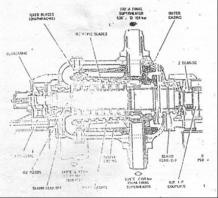
Figure 3. Tripple Turbine Casing
ad.2. Rotor
Turbine rotor consists of a shaft with rings formed from
a series of heated blades are aligned along the axis.
The rotor is the part of the turbine that converts the
energy contained in the steam into mechanical energy in the form of shaft
rotation.
In general there are two types of turbine rotor:
- Type rotor disk (Disk)
- Rotor drum
- Rotor disk type
On this type of rotor disks (Disk) is mounted on the
shaft to form a disc ranks as shown below
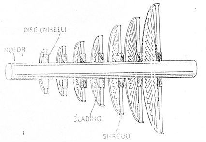
Figure 4. type disc rotor (disc)
- Rotor drum
This type of rotor, shaft casted and shaped as desired
and direct a series of blades mounted on a shaft. Rotor drum is very versatile
and can be worn almost all types of turbines.
As an illustration of this type of rotor can be seen in
the picture below
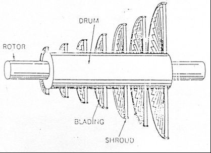
Figure 5. rotor drum
ad.3. Blade
is part of a turbine blade wherein the energy conversion
occurs on the blade itself consists of a blade root portion, the body blades
and blade tip as shown below
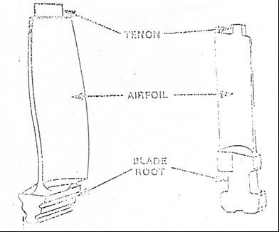
Figure 6. turbine blades
Blade as shown in Figure 6, then strung together to form
a full circle.
The existing series of blades that functioned as the
blade path and there are functionalized be fixed blade.
Series of blades mounted around a street circuit rotor
blades are fixed mounted around the inner casing. The series blade serves to
kinetic road steam into mechanical energy in the form of turbine shaft rotation.
Being fixed blade, in addition there is a function to convert heat energy into
kinetic energy, but there is also a function to reverse the flow direction of
steam. Examples of the blade series can be seen in the picture below
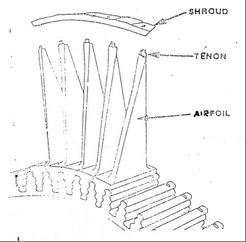
Figure 7. blade path
In figure 7 shows that the blade root section is drilled
into the grooves around the rotor, while the ends of the blades are united by a
plate bajapenghubung called Shroud.
Shroud serves to strengthen and reduce the vibration of a
series of blades. Fixed blades are generally arranged in a semicircle on a
segment called the diaphragm as terliahat in the picture below
Figure
8. Fixed blade
One segment of the diaphragm and then mounted on the
casing around the bottom being a partner dippasang diaphragm segments at
different parts of the upper casing.
When these two chassis together, between the diaphragm to
form a full circle.
In general there are two types of blades:
- Blade impulse
- Blade reaction
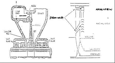
Figure 9. impulse blade
On impulse blade, the entire heat energy changes into
kinetic energy carried in fixed blade (nozzle).
When the blade across the road, the pressure did not
change and theoretically, the vapor pressure before the blade the same way with
the vapor pressure after the blade.
Because the turbine impulse pressure is often called
flat. Denagn Thus, the turbine shaft with blades impulses arise virtually no
axial force on the shaft.
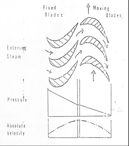
Picture 10. blade reaction
Being on the blade reaction, some of the energy is
converted into kinetic energy heat fixed and partly disudu disudu road.
Result: each blade through the ranks, the ranks of both
fixed blade and the blade line, vapor pressure will decrease. Consequences on
the turbine blades reactions, axial forces arise quite big on the rotor shaft.
ad.4. Cushion
as part of a rotating, the rotor has a tendency to move
in both radial and axial direction, because it's riveted rotor should be good
to avoid a shift of radial and axial overload. Diapkai component for this
purpose is called bearing (Bearing).
Steam turbines are generally equipped by:
- Bearing journals (journal bearing)
- Axial bearing (thrust bearing)
to support the rotor and rotor to shift mebatasi. Picture
below is an example of a typical bearing above.
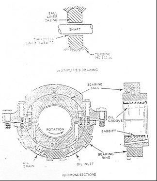
Picture 11. Cushion
On journal bearings, the inner surface of which may be in
direct contact with the surface of the metal shaft coated by white (white metal
/ Babbit) are soft. Besides, there is also a channel - the channel where the
lubricating oil to flow into the channel Diman Bantala and lubricating oil can
flow out left bearing.
While the axial bearing (thrust bearing) consists of a
disc umumya (thrust collar) which is part of the shaft and the two shoes
(thrust pad) attached to the casing. Axial bearing function:
- To control the axial position of the rotor relative to
the casing.
- Prevents the interface between the rotating part with a
stationary part.
Axial retaining Style
1. Dummy Piston / Piston Balancing
Directors at the turbine pressure drop occurs in each row
of blades - blade motion, will mengakibatka onset enormous force on the rotor
where the direction of the force is in line with the flow of steam.
So to reduce the load on the bearing axial (thrust) axial
force is balanced with a counterweight or a dummy piston piston mounted on the
turbine rotor.
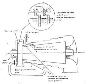
Image. Piston construction balancer
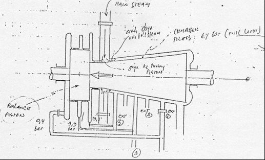
On the turbine casing which has a cylinder with double or
tripple dummy casing is connected to the piston-cylinder steam out, but on a
machine - a machine that old low-pressure side of the dummy piston cylinder low
pressure associated with.
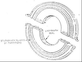
To reduce steam leakage at the edge of the dummy piston
seals fitted labyrint types.
On the high and low dummy mounted piston seals (seal
labyrint). Difference in surface area between the low pressure side and high
pressure side dummy piston gives rise to the pressure difference between the
two sides of the dummy piston.
Differences so as to produce sufficient thrust to offset
the effect of axial gay steam flow through the turbine blades.
If still no resultant force is usually small enough, then
this style will be muted by Bantala axial (thrust bearing) mounted on the front
turbine
Dummy piston is only required on turbine blade with
single wing type of reaction.
On the type of impulse turbine no vapor pressure
reduction in blade - blade motion.
To ensure this, it made a hole - the hole offsetting
pressure on the rotor rim.
The turbine - turbine flow like the IP cylinder and low
pressure cylinder (LP) arising force - axial force opposing directions.
Thus the force - axial forces will cancel each other out
with each other.
2. Bearing Axial (Thrust bearing)
Axial bearing construction which is widely used in steam
turbines:
- For the turbine shaft flexible coupling connected with
each spindle has its own axial bearing.
- For turbines with solid coupling mounted only one axial
bearing is usually placed between the cylinder the cylinder HP LP
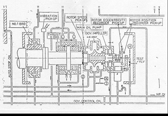
Image. Location Thrust Bearing
 Posted in: POWER PLANT


0 komentar:
Post a Comment
Thank you for your comment