Concentrated black liquor contains organic dissolved wood residue in addition to sodium sulfate from the cooking chemicals added at the digester. Combustion of the organic portion of chemicals produces heat. In the recovery boiler heat is used to produce high pressure steam, which is used to generate electricity in a turbine. The turbine exhaust, low pressure steam is used for process heating.
Combustion of black liquor in the recovery boiler furnace needs to be controlled carefully. High concentration of sulfur requires optimum process conditions to avoid production of sulfur dioxide and reduced sulfur gas emissions. In addition to environmentally clean combustion, reduction of inorganic sulfur must be achieved in the
char bed.
The recovery boiler process has several unit processes:
Combustion of organic material in black liquor to generate steam
Reduction of inorganic sulfur compounds to sodium sulfide, which exits at the bottom as smelt
Production of molten inorganic flow of mainly sodium carbonate and sodium sulfide, which is later recycled to the digester after being re-dissolved
Recovery of inorganic dust from flue gas to save chemicals
Production of sodium fume to capture combustion residue of released sulfur compounds
First recovery boilers
Some features of the original recovery boiler have remained unchanged to this day. It was the first recovery equipment type where all processes occurred in a single vessel. The drying, combustion and subsequent reactions of black liquor all occur inside a cooled furnace. This is the main idea in Tomlinson’s work.
Secondly the combustion is aided by spraying the black liquor into small droplets. Controlling process by directing spray proved easy. Spraying was used in early rotary furnaces and with some success adapted to stationary furnace by H. K. Moore. Thirdly one can control the
char bed by having primary air level at char bed surface and more levels above. Multiple level air system was introduced by C. L. Wagner.
Recovery boilers also improved the smelt removal. It is removed directly from the furnace through smelt spouts into a dissolving tank. Some of the first recovery units employed the use of Cottrell’s electrostatic precipitator for dust recovery.
Babcock & Wilcox was founded in 1867 and gained early fame with its
water tube boilers. The company built and put into service the first black liquor recovery boiler in the world in 1929.This was soon followed by a unit with completely water cooled furnace at Windsor Mills in 1934. After reverberatory and rotating furnaces the recovery boiler was on its way.
The second early pioneer, Combustion Engineering based its recovery boiler design on the pioneering work of William M. Cary, who in 1926 designed three furnaces to operate with direct liquor spraying and on work by Adolph W. Waern and his recovery units.
Recovery boilers were soon licensed and produced in Scandinavia and Japan. These boilers were built by local manufacturers from drawings and with instructions of licensors. One of the early Scandinavian Tomlinson units employed a 8.0 m high furnace that had 2.8*4.1 m furnace bottom which expanded to 4.0*4.1 m at superheater entrance.
This unit stopped production for every weekend. In the beginning economizers had to be water washed twice every day, but after installation of shot sootblowing in the late 1940s the economizers could be cleaned at the regular weekend stop.
The construction utilized was very successful. One of the early Scandinavian boilers 160 t/day at Korsnäs, operated still almost 50 years later.
Development of recovery boiler technology
The use of Kraft recovery boilers spread fast as functioning chemical recovery gave Kraft pulping an economic edge over sulfite pulping.
The first recovery boilers had horizontal evaporator surfaces, followed by superheaters and more evaporation surfaces. These boilers resembled the state-of-the-art boilers of some 30 years earlier. This trend has continued until today. Since a halt in the production line will cost a lot of money the adopted technology in recovery boilers tends to be conservative.
The first recovery boilers had severe problems with
fouling.
Tube spacing wide enough for normal operation of a coal fired boiler had to be wider for recovery boilers. This gave satisfactory performance of about a week before a water wash. Mechanical sootblowers were also quickly adopted. To control chemical losses and lower the cost of purchased chemicals
electrostatic precipitators were added. Lowering dust losses in
flue gaseshas more than 60 years of practice.
One should also note square headers in the 1940 recovery boiler. The air levels in recovery boilers soon standardized to two: a primary air level at the
char bed level and a secondary above the liquor guns.
In the first tens of years the furnace lining was of refractory brick. The flow of smelt on the walls causes extensive replacement and soon designs that eliminated the use of bricks were developed.
Improving air systems
To achieve solid operation and low emissions the recovery boiler air system needs to be properly designed. Air system development continues and has been continuing as long as recovery boilers have existed.As soon as the target set for the air system has been met new targets are given. Currently the new air systems have achieved low NOx, but are still working on lowering fouling. Table 1 visualizes the development of air systems.
Table 1: Development of air systems.
Air system
Main target
But also should
1st generation
Stable burning of black liquor
2nd generation
high reduction
Burn liquor
3rd generation
decrease sulfur emissions
Burn black liquor, high reduction
4th generation
low NOx
Burn black liquor, high reduction and low sulfur emission
5th generation
decrease superheater and boiler bank fouling
Burn black liquor, high reduction, low emissions
The first generation air system in the 1940s and 1950s consisted of a two level arrangement; primary air for maintaining the reduction zone and secondary air below the liquor guns for final oxidation.The recovery boiler size was 100 – 300 TDS (tons of dry solids) per day. and black liquor concentration 45 – 55 %. Frequently to sustain combustion auxiliary fuel needed to be fired. Primary air was 60 – 70 % of total air with secondary the rest. In all levels openings were small and design velocities were 40 – 45 m/s. Both air levels were operated at 150oC. Liquor gun or guns were oscillating. Main problems were high
carryover, plugging and low reduction. But the function, combustion of black liquor, could be filled.
The second generation air system targeted high reduction. In 1954 CE moved their secondary air from about 1 m below the liquor guns to about 2 m above them.The air ratios and temperatures remained the same, but to increase mixing 50 m/s secondary air velocities were used. CE changed their frontwall/backwall secondary to tangential firing at that time. In tangential air system the air nozzles are in the furnace corners. The preferred method is to create a swirl of almost the total furnace width. In large units the swirl caused left and right imbalances. This kind of air system with increased dry solids managed to increase lower furnace temperatures and achieve reasonable reduction. B&W had already adopted the three-level air feeding by then.
Third generation air system was the three level air. In Europe the use of three levels of air feeding with primary and secondary below the liquor guns started about 1980. At the same time stationary firing gained ground. Use of about 50 % secondary seemed to give hot and stable lower furnace.Higher black liquor solids 65 – 70 % started to be in use. Hotter lower furnace and improved reduction were reported. With three level air and higher dry solids the sulfur emissions could be kept in place.
Fourth generation air systems are the multilevel air and the vertical air. As the feed of black liquor dry solids to the recovery boiler have increased, achieving low sulfur emissions is not anymore the target of the air system. Instead low NOx and low carryover are the new targets.
Multilevel air
The three-level air system was a significant improvement, but better results were required. Use of CFD models offered a new insight of air system workings. The first to develop a new air system was Kvaerner (Tampella) with their 1990 multilevel secondary air in Kemi, Finland, which was later adapted to a string of large recovery boilers.Kvaerner also patented the four level air system, where additional air level is added above the tertiary air level. This enables significant NOx reduction.
Vertical air
Vertical air mixing was invented by Erik Uppstu.His idea is to turn traditional vertical mixing to horizontal mixing. Closely spaced jets will form a flat plane. In traditional boilers this plane has been formed by secondary air. By placing the planes to 2/3 or 3/4 arrangement improved mixing results. Vertical air has a potential to reduce NOx as staging air helps in decreasing emissions.In vertical air mixing, primary air supply is arranged conventionally. Rest of the air ports are placed on interlacing 2/3 or 3/4 arrangement.
Black liquor dry solids


Net heating values of industrial black liquors at various concentrations
As fired black liquor is a mixture of organics, inorganics and water. Typically the amount of water is expressed as mass ratio of dried black liquor to unit of black liquor before drying. This ratio is called the black liquor dry solids.
If the black liquor dry solids is below 20 % or water content in black liquor is above 80 % the net heating value of black liquor is negative. This means that all heat from combustion of organics in black liquor is spent evaporating the water it contains. The higher the dry solids, the less water the black liquor contains and the hotter the adiabatic combustion temperature.
Black liquor dry solids have always been limited by the ability of available evaporation.Virgin black liquor dry solids of recovery boilers is shown as a function of purchase year of that boiler.

Virgin black liquor dry solids as a function of purchase year of the recovery boiler
When looking at the virgin black liquor dry solids we note that on average dry solids has increased. This is especially true for latest very large recovery boilers. Design dry solids for green field mills have been either 80 or 85 % dry solids. 80 % (or before that 75 %) dry solids has been in use in Asia and South America. 85 % (or before that 80 %) has been in use in Scandinavia and Europe.
High temperature and pressure recovery boiler
Development of recovery boiler main steam pressure and temperature was rapid at the beginning. By 1955, not even 20 years from birth of recovery boiler highest steam pressures were 10.0 MPa and 480oC. The pressures and temperatures used then backed downward somewhat due to safety.By 1980 there were about 700 recovery boilers in the world.

Development of recovery boiler pressure, temperature and capacity.
Safety
One of the main hazards in operation of recovery boilers is the smelt-water explosion. This can happen if even a small amount of water is mixed with the solids in high temperature. Smelt-water explosion is purely a physical phenomenon. The smelt water explosion phenomena have been studied by Grace.By 1980 there were about 700 recovery boilers in the world.The liquid - liquid type explosion mechanism has been established as one of the main causes of recovery boiler explosions.
In the smelt water explosion even a few liters of water, when mixed with molten smelt can violently turn to steam in few tenths of a second.
Char bed and water can coexist as steam blanketing reduces heat transfer. Some trigger event destroys the balance and water is evaporated quickly through direct contact with smelt. This sudden evaporation causes increase of volume and a pressure wave of some 10 000 – 100 000 Pa. The force is usually sufficient to cause all furnace walls to bend out of shape. Safety of equipment and personnel requires an immediate shutdown of the recovery boiler if there is a possibility that water has entered the furnace. All recovery boilers have to be equipped with special automatic shutdown sequence.
The other type of explosions is the combustible gases explosion. For this to happen the fuel and the air have to be mixed before the ignition. Typical conditions are either a blackout (loss of flame) without purge of furnace or continuous operation in a substoichiometric state. To detect blackout flame monitoring devices are installed, with subsequent interlocked purge and startup. Combustible gas explosions are connected with oil/gas firing in the boiler. As also continuous O2 monitoring is practiced in virtually every boiler the noncombustible gas explosions have become very rare.
Modern recovery boiler
The modern recovery boiler is of a single drum design, with vertical steam generating bank and wide spaced superheaters. This design was first proposed by Colin MacCallum in 1973 in a proposal by Götaverken (now Metso Power inc.) for a large recovery boiler having a capacity of 4,000,000 lb of black liquor solids per day for a boiler in Skutskär, Sweden, but this design was rejected as being too advanced at that time by the prospective owner. MacCallum presented the design at BLRBAC and in a paper "The Radiant Recovery Boiler" printed in Tappi magazine in December 1980. The first boiler of this single-drum design was sold by Götaverken at Leaf River in Mississippi in 1984. The construction of the vertical steam generating bank is similar to the vertical economizer. Vertical boiler bank is easy to keep clean. The spacing between superheater panels increased and leveled off at over 300 but under 400 mm. Wide spacing in superheaters helps to minimize fouling. This arrangement, in combination with sweetwater attemperators, ensures maximum protection against corrosion. There have been numerous improvements in recovery boiler materials to limit corrosion.
The effect of increasing dry solids concentration has had a significant effect on the main operating variables. The steam flow increases with increasing black liquor dry solids content. Increasing closure of the pulp mill means that less heat per unit of black liquor dry solids will be available in the furnace. The flue gas heat loss will decrease as the flue gas flow diminishes. Increasing black liquor dry solids is especially helpful since the recovery boiler capacity is often limited by the flue gas flow.

A modern recovery boiler consists of heat transfer surfaces made of steel tube; furnace-1, superheaters-2, boiler generating bank-3 and economizers-4. The steam drum-5 design is of single-drum type. The air and black liquor are introduced through primary and secondary air ports-6, liquor guns-7 and tertiary air ports-8. The combustion residue, smelt exits through smelt spouts-9 to the dissolving tank-10.
The nominal furnace loading has increased during the last ten years and will continue to increase. Changes in air design have increased furnace temperatures.This has enabled a significant increase in hearth solids loading (HSL) with only a modest design increase in hearth heat release rate (HHRR). The average flue gas flow decreases as less water vapor is present. So the vertical flue gas velocities can be reduced even with increasing temperatures in lower furnace.
The most marked change has been the adoption of single drum construction. This change has been partly affected by the more reliable water quality control. The advantages of a single drum boiler compared to a bi drum are the improved safety and availability. Single drum boilers can be built to higher pressures and bigger capacities. Savings can be achieved with decreased erection time. There is less tube joints in the single drum construction so drums with improved startup curves can be built.
The construction of the vertical steam generating bank is similar to the vertical economizer, which based on experience is very easy to keep clean.Vertical flue gas flow path improves the cleanability with high dust loading.To minimize the risk for plugging and maximize the efficiency of cleaning both the generating bank and the economizers are arranged on generous side spacing. Plugging of a two drum boiler bank is often caused by the tight spacing between the tubes.
The spacing between superheater panels has increased. All superheaters are now wide spaced to minimize fouling. This arrangement, in combination with sweetwater attemperators, ensures maximum protection against corrosion. With wide spacing plugging of the superheaters becomes less likely, the deposit cleaning is easier and the sootblowing steam consumption is lower. Increased number of superheaters facilitates the control of superheater outlet steam temperature especially during start ups.
The lower loops of hottest superheaters can be made of austenitic material, with better corrosion resistance. The steam velocity in the hottest superheater tubes is high, decreasing the tube surface temperature. Low tube surface temperatures are essential to prevent superheater corrosion. A high steam side pressure loss over the hot superheaters ensures uniform steam flow in tube elements.
Future prospects
Recovery boilers have been the preferred mode of
Kraft mill chemical recovery since the 1930s and the process has been improved considerably since the first generation. There have been attempts to replace the Tomlinson recovery boiler with recovery systems yielding higher efficiency. The most promising candidate appears to be gasification,where
Chemrec's technology for
entrained flow gasification of black liquor could prove to be a strong contender.
Even if new technology is able to compete with traditional recovery boiler technology the transition will most likely be gradual. First, manufacturers of recovery boilers such as
Metso,
Andritz and
Mitsubishi, can be expected to continue development of their products. Second, Tomlinson recovery boilers have a long life span, often around 40 years, and will probably not be replaced until the end of their economic lifetime, and may in the meantime be upgraded at intervals of 10 – 15 years.
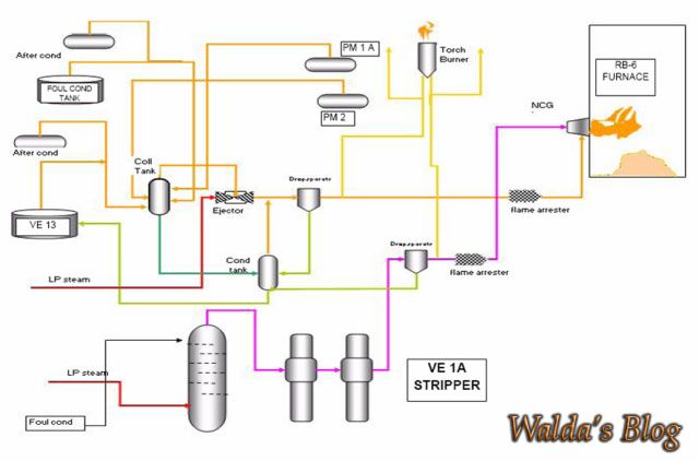
see also previous article
"Ncg (non condensible gases)"
May be useful.

 WORLD RECORD RB - 6 ABLE " RUNNING " 365 DAYS ( 12 MONTH MORE )
 Sunday, November 24, 2013
 Unknown

 Recovery Boiler - 6 is one of the two boiler units operating in the RB - 1 ( RB
- 5 and RB - 6 ) . Boiler is located in the area currently only Riau.And
Recovery boiler - 6, listed as one of the boilers are capable of operated for
365 days , 12 months without any stop engine and trip since September 10, 2012
until now .
Recovery Boiler - 6 is one of the two boiler units operating in the RB - 1 ( RB
- 5 and RB - 6 ) . Boiler is located in the area currently only Riau.And
Recovery boiler - 6, listed as one of the boilers are capable of operated for
365 days , 12 months without any stop engine and trip since September 10, 2012
until now .


