
 OPERATION OF VACUUM SYSTEM
 Monday, April 15, 2013
 Unknown

3.6.1 Start Vacuum
System
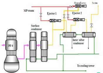
To arouse a vacuum in the evaporator used a tool called Ejector.


2. Protective Goggles

3. Gloves

4. Protective Shoes

To arouse a vacuum in the evaporator used a tool called Ejector.
If
Black Liquor is charged each effect and Cooling water was circulated on
Surface condensers and after / inter condenser, the vacuum system can be
operated with the following procedures:
1. Open the manual valve inlet Primary and secondary steam
ejector
2. Open the manual valve inlet vapor ejector Hoging
3. Open the manual valve inlet steam ejector hoging
4. Close bypass valve vacuum breaker
5. If the vacuum in the PF-6 has been achieved -700 mbar
Hoging cap ejector and ejector Primary and secondary roads remain

3.7 Procedure Start
Evaporator
1. Charging Black
Liquor into effect
• Start the pump WBL Feed
• Set the flash tank feed flow to approximately 30% of the
design by adjusting the control valve WBL feed
• Raise the level of PF-6 to 80% and then start the
circulation pump PF-6.
• Start Transfer pump PF-6 and set the level controller with
set point 50% of auto
• Then Black Liquor will go to PF-5, and repeat the
procedure as PF-6 for each effect 5, 4 effect, effect 3 and effect 2,
• If the Black Liquor has reached PF-2, select the PF1
sequence (eg ABC) and the valve-open valve in accordance with the order of
sequence.
• Start Transfer pump PF-2 and set the level of 50% Auto
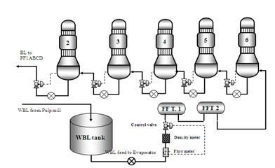
Figure 3.14 Cycle Black Liquor from WBL tank to the PF-2
• Raise the level of PF-1A to 80% and then start the
circulation pump PF-1A
• Setting the level of PF-1A 50%
• Perform the same procedure for filling PF and PF-1B-1C
• Black Liquor Spill circulated to the tank or tank WBL
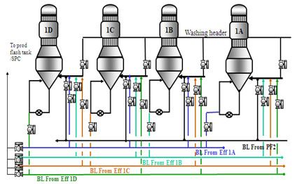
Figure 3.15 Cycle Black Liquor on the PF-1A, PF-1B,-1C PF,
PF-1D
2. Operation of Steam
and Condensate LP
If the vacuum in the PF-6 has been achieved -750 mbar the LP
steam to PF-1 can dibuka.dengan following steps:
1. Make sure the vapor control valve to open ABC PF-1 to
approximately 50%
2. Make sure the condensate level pot for PF-normal 1ABC
Auto position set point 50%
3. Make sure the condensate flash tank pump ready and
conductivity meter to function properly
4. Open the Manual Valve LP steam for PF-1ABC 100%
5. Open the LP steam control valve for PF-1ABC approximately
20% or LP steam flow set around 20 tonnes for each Effect 1ABC
6. Set desuperheater control valve to the Auto position set
point around 135 s / d 140oc
7. If the condensate level has appeared in Flash Condensate
tank, start the pump and condensate pump control valve set to 50% of auto
8. Change the position of the on-off valve condensate to
Sequence
9. If steam has entered the Effect 1 then evaporation will
occur at each effect and the condensate will occur
10. If an indication of the level of the Clean condensate
flash tanks have emerged, Start clean condensate flash tank pump, then set Auto
level controller to position the set point of 50% and set the on-off valve to
the position of Sequence.
11. Note the level on Foul condensate flash tank, if the
level has emerged pump start Foul condensate flash tank, then set the level
controller to Auto position set point 50%
12. Adjusts the on-off valve to the Sequence (if high
conductivity will automatically go to the spill tank)
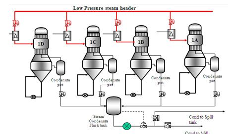
Figure 3.16 Cycle LP Steam and Condensate in PF-1
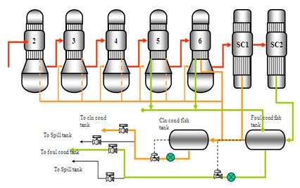
Figure 3.17 Cycle Vapor and Condensate
3. Operation Stripper
Stripper is a tool that serves to purify Foul condensate by
way of separation of the gases in the foul condensate to be burned again in RB
/ RC.
• Operating procedures Stripper system:
1. Make sure all equipment is ready to operate on stripper
2. Foul condensate tank pump start and open the outlet valve
of the field manual
3. Open the control valve to the foul condensate Striping
column and set the flow to approximately 70 m3 / H
4. If the level has appeared at the bottom of the stripping
column start stripping column and set the pump control valve position set point
Auto with 50%
5. Open Black Liquor incoming Reflux condenser (with manual
valve open inlet and outlet reflux condenser).
6. Open the control valve outlet NCG Trim condenser approximately
25% and manual valve inlet flame arresters and make sure the path is open all
the way NCG NCG burner or by pass into the atmosphere.
7. Open warm water condenser inlet and outlet Trim
8. Open the LP steam or vapor into stripping column as needed
or loaded with foul condensate ratio to 1:5 ton steam
9. Start pumping condensate pot if indications have appeared
on the tank level and control level set to Auto position set point of 50%.
10. Set out with a press NCG NCG set the control valve
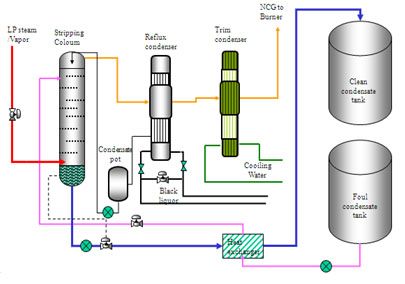
Figure 3.18 Process flow on Stripper
3.8 Personal
Protective Equipment
Personal Protective Equipment used in the field Vacuum
Evaporator:
1. Helm

2. Protective Goggles

3. Gloves

4. Protective Shoes

 Posted in: POWER PLANT


0 komentar:
Post a Comment
Thank you for your comment