web widgets

07 March, 2013

TOO LITTLE OR EQUALLY MOST DANGEROUS SPORTS FOR KNEE

Lack of physical activity in middle age may cause the deterioration of cartilage in the knee and the risk of knee osteoarthritis. But based on research, too much physical activity in this age also have the same risks.

A new study says that high levels of physical activity and low, they may accelerate cartilage damage to the knee in adults who have middle-aged.

Researchers at the University of California San Francisco (UCSF) have previously found an association between physical activity with cartilage degeneration. However, the study only focused on one point of time.

UCSF researchers see changes in knee cartilage in a group of middle-aged adults during the 4-year study period. Researchers used magnetic resonance imaging (MRI)-based T2 relaxation time (part-time) to track the evolution of early degenerative changes in the knee cartilage.

"T2 relaxation time produced by MRI allows for the analysis of biochemical and molecular composition of cartilage. An increase in water mobility in damaged cartilage, and the resulting increase in water mobility increased T2 relaxation time, "Wilson said Lin, who led the study.

Researchers analyzed 205 patients aged 45 to 60 years, from UCSF Osteoarthritis Initiative, a national study funded by the National Institutes of Health for the prevention and treatment of knee osteoarthritis.
Participants were asked to fill out questionnaires to record their physical activity then researchers measured T2 values ​​of cartilage in the femur, tibia and patella of the right knee joint at baseline, 2-year and 4-year study at the end of the study.

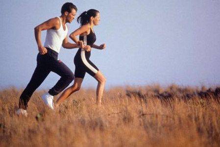
According to the study, people who often participate in sports such as running with high intensity, have been associated with a more degenerate cartilage and increased risk for development of osteoarthritis.

06 March, 2013

7 SIGNS YOUR OBSESSION ON SPORTS CAN BE DANGEROUS BODY


Maintain health and fitness to sports or physical exercise is very important. But if exercise is done too much to memforsir power, which happens not to be healthy but health problems. These are the signs you exercise excessively and should be immediately wary, quoted from Time Gal.

1. Not Compromise on Health
There are times when the schedule is very solid routines so hours of sleep is reduced and the body was not fit. If you are experiencing now feel guilty for not being able to exercise, it is a problem that must be avoided. When you are injured, have a fever or lack of sleep but still think going to the gym is very important, it has become a problem that must be addressed. Regular exercise is necessary, but not what the occasional sports schedules passed.

2. Exercise is a Liability
Although the workout at the gym can make you feel happy, but it should not be a liability. Do exercise at intervals should be, because if it is too demanding it every day then it is not fun anymore training activities.

3. Calorie is the Enemy
If every time you eat foods calculate how long it takes to burn calories back, then maybe you are obsessed. Avoid the need not worry too much about calories into the body because the body also needs calories for energy.

4. Down Drastic Weight Loss
Someone who are obese tend to lose weight drastically when beginning a diet and exercise. In fact, the weight loss of more than 1.3 kg per week then it means you push yourself too hard.

5. Not Balanced
Do not get a solid workout schedule snatch happiness because it must pass through a preferred activity. Take the time to socialize with friends or family because it is not as important as exercise.

6. Prone to Injury
People who are prone to diligent exercise because muscle injury that kept working. If the center was injured, do not force yourself to exercise regularly but istirahatkanlah yourself so that you can recover health.

7. Run out of steam

Sports provide power is indeed a fact. However, if excessive exercise will harm you.

12 August, 2012

WHAT IS THE RECOVERY BOILER?

Definition Recovery Boiler

Recovery Boiler A boiler is a special unit used to purify the compound - an organic chemical compounds contained in Black Liquor (waste cooking from the digester) and at the same time as high-pressure steam generator (High Pressure Steam).
Heavy Black Liquor (70% solid) containing:
An organic compound with the main content of Na2CO3, Na2SO4, NaOH, Na2S.
Organic compounds derived from wood during cooking in the digester in the form of wood fibers, ligmin
Water
Heat energy contained in the Heavy Black Liquor range 3100 - 3500 kcal / kg dry solid.
Heat energy is partly used to convert the organic compounds and partly used as fuel to generate steam
Heavy Black Liquor Evaporator Vacuum produced by the input to the Mixing Tank, in the mixing tank mixed with combustion ash from ESP (Electrostatic precipitator) and-1 from the economizer, economizer-2, Boiler Bank, then added with salt cake (Na2SO4 powder).
Once mixed in the Mixing Tank, Heavy Black Liquor (HBL) is sprayed into the furnace to burn through the spray gun. Prior to the furnace going process of drying by blowing hot air, then collects in the bottom of the furnace to form charbed and caught fire after reaching the point of combustion.
Combustion air needs exhaled through the Primary, Secondary and Tertiary wind boxes located around the bottom of the furnace wall.


To start combustion in the furnace as well as to stabilize the combustion conditions, use of diesel fuel is sprayed through a burner into the furnace.
During combustion, the following process takes place in the furnace are:
1. The compound - organic compound burning releases heat and partly turned into a gas.
2. Sodium sulphate (Na2SO4) contained in the HBL and the salt cake is reduced to a compound of sodium sulphite (Na2S)
Na2SO4 + 2C + 2 Co2 Ns2S
The speed reduction is calculated:
Reduction Rate: Na2S. X 100%
Na2S + Na2SO4
3. The compound - an organic compound called Smelt melt like lava.
If the conditions of combustion is complete, reduction rate reached> 95%
A melt of organic chemicals (smelt) will accumulate around the side charbed smelt spout and flow out into the dissolving tank, where in the dissolving tank, smelt will be dissolved with WLL (WEAK White Liquor) from RC, the mixture of smelt with the WLL-called Green liquor (GL) which is pumped from the dissolving tank RB to RC section for the Recausticyzing be WL (White Liquor) or cooking liquor
For reuse as raw wood cooking in digester (Pulp Making Section)

Time of air and gases - gases of combustion, called flue gas still contains a high amount of heat Energy.
Flue gas is inhaled / drawn by a device called the Induced Draft Fan (IDF), where the flue gas will pass through the pipe - boiler pipe so that water contained in boiler piping briefly - of land become heated and turned into high-pressure steam will then be used for the propulsion of Turbine Generator to generate electrical energy.
So the production side of the Recovery Boiler is STEAM high pressure (60 bar)

Smelt Reduction Efficiency:
Na2SO4 + 2C + Heat ----- Na2S + 2CO2
SRE = Na2S/Na2S + Na2SO4 x 100%
Recauticizing
--- CaO + H2O Ca (OH) 2
Ca (OH) 2 + Na2CO3 --- 2NaOH + CaCO3
CaCO3 + Heat ----- CaO + CO2

History of Recovery Boiler

Kraft Porridge was first developed in Germany in 1870's, in a strong sense in Germany: kraft pulp fiber slurry to produce hard at a short maturation process.
Addition of Na2SO4 will be accelerated with delignification process without reducing the strength of pulp fibers.
Pulp first made in 1909 in the city Roanake Rapids, North Carolina, kraft pulp growing popularity, in 1930 to found the Recovery Boiler is made more economical kraft pulp.
Today kraft pulp about 70% is produced in America.

Feed Water to Steam Cycle Recovery Boiler 6
Demineralizer water (steam PG) Feed Water Tanks economizer economizer 1 2 Dolezal (to RB & RB-6-12) Steam drum bottom of steam drum to the boiler wall piping, furnaces & Steam Boiler drum bank top to the screen tube Primary Secondary superheater superheater Tertiary superheater steam to the turbine generator.

Park Pressure Recovery Boiler
1. Furnace site of a combustion process HBL
2. Superheater is placed over the furnace, and the screen is protected with a nose tube.

Nose is designed to produce flue gas flow pressure of a strong and directed to the superheater, as well as to protect the superheater from the excess. Then superheater which comes from the furnace to the superheater. This event continues from primary superheater, secondary and tertiary superheater superheater.
3. Screen Tube
To avoid direct heat flue gas coming from the furnace to the superheater and the lower the temperature of the furnace by means used by the screen tube.
4. Boiler Bank
Its location is situated behind the superheater.
5. Economizer
Economizer economizer consists of 1 & 2 is the long stream counter flow between the flow of flue gas and feed water

Factors Supporting Recovery Boiler

1. Soot Blowing System
Aims to bring down the soot blowers or clean ash piping attached to the inside of the boiler (superheater, boiler bank, economizer).
RB-6, has 86 sets Sootblower (43 to the left, 43 top right)
2. Medium Pressure Steam
For Air preheater, start-up burner, smelt spout steam shuttering.
3. Low Pressure Steam
For water preheater
4. Condensate
5. Electrostatic precipitator (ESP)
Each RB must be equipped with ESP which is useful for capturing particles - solid particles contained in the flue gas further solid particles (ash) is returned to the mixing tank to be mixed with HBL
RB-5 Equipped with 2 sets ESP
RB-6 & 12 are equipped with 3 sets ESP
RB-11 is equipped with 4 sets ESP

Recovery Boiler is also equipped with security system

1. Interlock System
This system serves to prevent damage in case of irregularities Boiler operating conditions.
2. Safety Valve
This tool serves to keep the boiler pressure does not exceed the limits specified security pressures.
3. Rappid Drain System.
This system serves to empty the water boiler to a minimum label, if there is a severe leakage in the piping boiler causing water to enter into the furnace.
This system operated at the time of emergency and went so fast for Boilers avoid further damage.

RB Quality Control

1. Demineralizer Water Conductivity pH 6.0 ~ 8.0 <5.0 ms / cm 2. Feed Water Conductivity pH 8.0 ~ 9.5 <5.0 ms / cm SiO2 <40.0 ~ 50.0 ppb 10.0 ppb N2H4 3. Boiler water pH 9.5 ~ 10.5 Conductivity <150.0 mx / cm PO4 2.0 ~ 12.0 ppm SiO2 <3:50 ppm 4. Saturated Steam Conductivity pH 7.5 ~ 9.5 <5.0 ms / cm SiO2 <40.0 ppb 5. Steam superheater Conductivity pH 7.5 ~ 9.5 <5.0 mx / cm SiO2 <40.0 ppb 6. Green Liquor NaOH 12.0 ~ 20.0 g / l Na2S 25.0 ~ 35.0 g / l Na2CO3 70.0 ~ 85.0 g / l TSS <1500 ppm 7. Smelt Reduction rate> 95.0%.see also previous article"How does a power plant boiler work?".

10 August, 2012

HOW DOES A POWER PLANT BOILER WORK


This time articel is i will study about how recovery boiler work. after yesterday I was talking about "THE ELECTROSTATIC PRECIPITATOR".The boiler generates high pressure steam by transfering the heat of Combustion in various heat transfer sections. This part of the article series briefly describes the flow and arrangement of the heat transfer sections in a boiler. In line diagrams help make the concept clear. The Basics. Volume of one unit mass of steam is thousand times that of water, When water is converted to steam in a closed vessel the pressure will increase. Boiler uses this principle to produce high pressure steam. Conversion of Water to Steam evolves in three stages. • Heating the water from cold condition to boiling point or saturation temperature – sensible heat addition. • Water boils at saturation temperature to produce steam - Latent heat.addition. • Heating steam from saturation temperature to higher temperature called Superheating to increase the power plant output and efficiency. Sensible Heat Addition Feed Water Pump. The first step is to get a constant supply of water at high pressure into the boiler. Since the boiler is always at a high pressure. ‘Boiler feed water pump’ pumps the water at high pressure into the boiler from the ‘feed water tank’. The pump is akin to the heart in the human body. Pre-Heating 'Feed water heaters’, using extracted steam from the turbine, adds a part of the sensible heat even before the water enters the boiler. Economiser. Most of the sensible heat is absorbed in the Economiser. These are a set of coils made from steel tubes located in the tail end of a boiler. The hot gases leaving the boiler furnace heat the water in the coils. The water temperature is slightly less than the saturation temperature. From the economiser the water is fed to the 'drum'. Pre-Heating & Economiser Latent Heat Addition Drum. The drum itself a large cylindrical vessel that functions as the storage and feeding point for water and the collection point for water and steam mixture. This is the largest and most important pressure part in the boiler and weighs in the range 250 Tons for 600 MW power plant. Water Walls Boiling takes place in the ‘Water Walls’ which are water filled tubes that form the walls of the furnace. Water Walls get the water from the ‘downcomers’ which are large pipes connected to the drum. The downcomers and the water wall tubes form the two legs of a water column. As the water heats up in the furnace a part of the water in the water-wall tubes becomes steam. This water steam mixture has a lower density than the water in the downcomers. This density difference creates a circulation of water from the drum, through the downcomers, water walls and back to the drum. Steam collects at the upper half of the drum. The steam is then sent to the next sections. The temperature in the drum, downcomers and water wall is at the saturation temperature. WaterWalls SuperHeat / ReHeat SuperHeater Steam from the drum passes to the SuperHeater coils placed in the Flue gas path.. The steam temperature increases from the saturation temperature till the maximum required for operation. The superheated steam then finally goes to the turbine.Final Superheater temperatures are in the Range of 540 to 570 °C for large power plants and SuperHeated steam pressures are around 175 bar. Reheater Steam from the exhaust of the first stage turbine goes back to the boiler for reheating and is returned to the second stage. Reheater coils in the flue gas path does the reheating of the returned steam. The reheat steam is at a much lower pressure than the super heated steam but the final reheater temperature is the same as the superheated steam temperature. Reheating to high temperatures improves the output and efficiency of the Power Plant. Final Reheater temperatures are normally in the range of 560 to 600 °C. Reheat steam pressures are normally around 45 bar. SuperHeater / ReHeater The above are the major water and steam circuit items in a boiler and are collectively called the ‘pressure parts’.
see also previous article "What is the electrostatic precipitator ?"
Maybe Useful.

26 July, 2012

MECHANISMS OF STEAM SOOT BLOWER EROSION

There are many mechanisms that can cause steam soot blower erosion of boiler tubes at various heat transfer sections. Knowing the way these mechanisms contribute to erosion will help to prevent loss of availability of boiler.

Soot blowers are provided in boilers at various locations like water-walls, superheaters, reheaters, economizers and air pre-heaters. Steam soot blowers have specific advantage and disadvantages over other types. The advantages being mainly their low capital cost, operating cost and the effectiveness of cleaning in areas like furnace, superheaters and reheaters.

The major disadvantages are they need a higher level of maintenance; effectiveness is low in oil firing mainly in air pre-heater area. They need warm up and condensate draining before startup. The mechanisms of steam soot blower erosion of heat transfer tubes can be a single factor or multiple factors acting individually or in unison. There are much more than hundred soot boilers in boilers generating and supplying steam for a 500 MW and above plants.
Possible mechanisms
  • All blowers are set to be set at the right steam pressure recommended by the designer if this is not done then it leads to poor cleaning or higher rate of tube erosion due to high steam pressure. This is true for all soot blowers in the boiler starting from furnace to air pre-heater.
  • The alignment of the blower with respect to the furnace walls, superheater tubes, reheater tubes, economizer tubes and air pre-heater tubes or elements is very critical and not maintaining this leads to erosion of the tubes and subsequent metal wastage. The thinning of the tubes finally leads to pinhole failures and many secondary figures due to this depending upon the orientation of the leak.
  • It is required to ensure at least 50 degree centigrade of super heat in the steam being used for blowing. If the super heat in the steam is lower than required then during blowing wet steam impinge the tubes at high velocity and the impact force damaging the heat transfer tubes. This can be identified by the typical spit like metal wastage on the tubes surrounding the blower’s area of effectiveness.
  • The duration of operation of blowers is another main reason for erosion of the heat transfer tubes. Even if you maintain the correct pressure and temperature the erosion will take place at a slow phase if duration is more than required.
  • In coal fired boiler if alignment is not correct then the ash deposits being cleaned can get entrained and cause erosion of tubes. However in oil fired boilers it is not a mechanism that can happen due to the fact that the ash in oil is not significant at all.
  • The higher frequency of operation of the soot blowers than needed also leads to tube erosion.
  • Optimizing the soot blower operation is important as operating those blowers where deposits are not there or very low will lead to metal wastage over a period of time.
  • Failure to drain the condensate in the soot blower steam pipes is also contributing mechanism of tube erosion. The condensate gets entrained in the steam while the blower operates and has a much higher damaging effect than the lower degree of superheat in steam.
It has been seen in many boilers, mainly coal fired boilers, the soot blower erosion is one of the main contributing factors for loss of boiler availability. In the case of chemical recovery boilers also the soot blowers attribute to the loss of availability of boiler in a significant way

Soot blowers keep the heat transfer surfaces in a boiler clean. A brief description of the working of soot blowers is given in this article.

Chimney Sweeps have been legendary characters in English literature from Hans Christian Anderson to Charles Dickens. In the earlier days when houses had fireplaces, the Chimney Sweep did the function of cleaning the soot from the chimney. In the modern day boiler, the soot blower does the same function.
In oil fired boilers, over a period of time the heat transfer tubes get covered by a layer of soot or fine carbon deposit. This reduces the heat transfer from the hot gases to the water and reduces the efficiency of the boiler.
In coal fired boilers, the furnace area gets covered by slag which is molten ash. The ash also sticks to the heat transfer surface in the other heat transfer areas. These ash accumulations reduce heat transfer and increase the tube metal temperatures leading to failure of the tubes.
.
Tube cleaning is done periodically to remove the ash or soot deposits. Steam is the medium used for cleaning. The steam is taken from the boiler itself.
The soot blower consists of a lance tube with a nozzle at the end. When it is operated, the lance is extended into the boiler and steam is admitted through the lance. The steam comes out as a high velocity jet through the nozzles, which cleans the ash deposited on the surface. When the lance moves into the boiler it is also rotating so that it cleans the sweeping area covered by the circular travel of the nozzle. The lance is then retracted back.

There are two types of soot blowers.
  • One with a very long lance called the “long retractable soot blowers.” This is normally used to clean the ash deposit from between the coils of superheaters and economisers.
  • The other type is the shorter lance type called the “wall blowers.” These are used to clean the furnace walls. The lance extends a short distance around 200 mm from the furnace wall. The nozzle direction is such that the steam impinges on the walls cleaning the surface. During operation, the lance rotates cleaning the radial area covered by the steam from the nozzle.
The deposits on the walls are due to the chemical constituents of ash, and the amount of combustion air. If the ash contains more of Ferrous Sulphide, then the melting temperature of the ash is low which makes the ash melt and stick to the walls.
A large coal fired Thermal power plant will have around two hundred soot blowers of both types arranged to cover all the area of the boiler. This will be programmed to automatically operate to a required sequence.
Intelligent soot blower systems calculate the trends in the temperature increase in different sections of a boiler. The program then decides which soot blowers have to be operated and at what frequency.
High-pressure water lances are also used in some units where the slagging is very heavy.
see also previous article "What is the black liquor?"
May be useful.


.

23 July, 2012

FURNACE CAMERA


This day i will taking about Furnace Camera.As the current technological developments in power plant technology especially the use of recovery boiler is constantly innovating in order to complement the existing deficiencies in the means of production to facilitate the operation of the recovery boiler.
Currently the power plant that uses a recovery boiler there is a lack of technology to the unavailability of a device to control the conditions inside the boiler (furnace). So far the recovery boiler operator can only monitor the condition of the inside of the furnace manually just by looking at the field by controlling the air of room pannel (dcs). but that's not enough data taken with the actual data. accuracy conditions may only be 65% to monitor conditions inside the furnace charbed.


Camera Enclosure with Lens

The above shows what is removed and store during shutdown or repair


Camera Enclosure Interior


Back of camera core


Removing Camera Core

Camera Retract system


Camera Port

Cleaner


Control Enclosure

Solenoid valve assembly
(Inside control enclosure)


Valve Manual override
Siemens LOGO PLC


Settable Parameter available from key pad on Logo:
Cycle time (time between cleaning cycles)
Cleaning stroke time (time energized and de-energized
Number of cleaning strokes


Pneumatic System
Lens tube/manifold pressure to be maintained between 1.5 and 2 BAR
Input pressure to the system should be 5 and 12 bar

The cleaning cylinder (with check valve) acts as an accumulator to retract camera in the event of a line failure.


System Faults and General Maintenance

LENS CLEANING


The most common form of maintenance on the camera lens system will be cleaning the “objective” lens – that part of the lens system furthest from the camera. Periodic, daily cleaning of the objective lens should be expected, although cleaning intervals of 5 or 6 days are not un-common.
A dirty objective will produce an image that is fuzzy or appears out of focus. The part of the objective that requires cleaning is the protective clear sapphire window, which is very hard and difficult to inadvertently scratch, but relatively easy to break.
Warning:
Do not attempt to clean a hot lens! The objective lens assembly must be below 110°F or comfortable to the touch before cleaning.
To clean the objective lens sapphire:
Retract the lens by selecting “RETRACT” at the control enclosure.
Allow the lens to cool for several minutes.
Once cool (relatively comfortable to the touch), turn the supply air to the lens system off at the shut-off valve.
Using a cotton swab and alcohol, reach into the end of the lens assembly and clean any dirt or oil that may have collected on the objective sapphire.
Char build-up on or around the lens tube should also be cleaned at this time.
Turn the supply air on.

Most Faults and the probable reason for the fault are broadcast on the face of the Control Panel


The camera has 30-seconds to cool down once an overtemp
Situation is discovered.
There are three different faults that will cause the camera to retract:
Camera enclosure over temp - temporary over temp recognized
Camera has retracted and then cooled to operating temp check air supply and for combustion air leaks
Camera over temp - system is shut down
Camera retracted and failed to cool within 30 seconds camera has been shut off as result to avoid damage. Check air supply and cooler adjustment.
Low air pressure – camera retracted to avoid overheating
Check for compressed air leaks and ball valve position
Retract limit fail – automatic cleaning not possible
Important to keep the retract cleaned and lubricated so if a overtemp condition occurs the retract can do what it is supposed to do
Output fail check fuse 1
Output fail check fuse 2
Output fail check fuse 3
There are three different ouput faults that are monitored
Maybe usefull.

 
Design by Afridal Walda | Directed by Afridal Walda - Walda's Blog | Blog that provides information about the Recovery Boiler and supporting parts